Login
You're viewing the pawb.fun public feed.
  • Nov 11, 2026, 11:48 AM

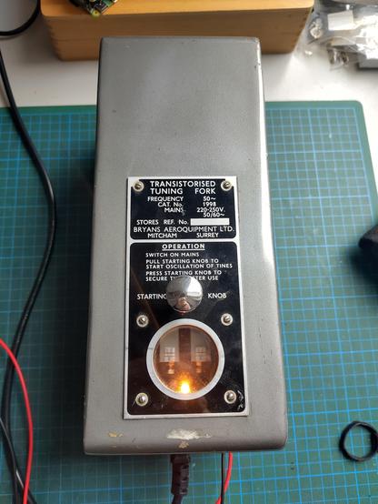
    after getting nerdsniped into the whole power line frequency monitoring thing by @x44203 I decided that instead of monitoring the same power network as anyone else I'd hook up this thing and see how stable it is.

    Photo of a large gray box with a name plate reading "Transistorised Tuning Fork". There is a small window in the name plate showing what appears to be two large tines of a very large tuning fork illuminated by a small light bulb
    💬 3🔄 7⭐ 27

Replies

  • Nov 11, 2026, 12:29 PM

    freq: 50.009522391407444, avg:50.010218546801035, stddev:0.001176184258215776

    💬 2🔄 0⭐ 5
  • Nov 11, 2026, 6:14 PM

    well, it's more stable than the mains frequency at least, so that's something!

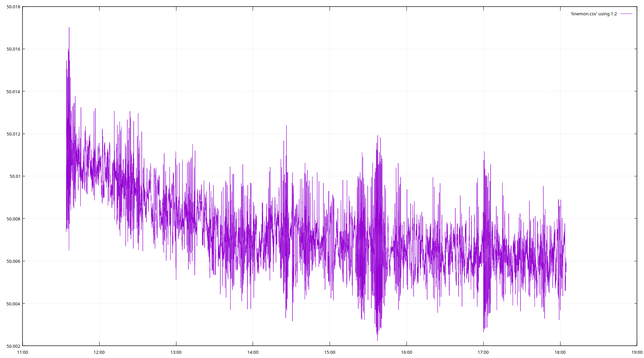
    you can see the frequency drop for quite a while as the thing slowly warms up before it kinda settles. it's still kinda noisy though and there are some interesting bursts of noise.

    graph showing the frequency of the tuning fork oscillator over a time of around 6.5 hours. it starts off at around 50.011Hz and then slowly drops before setting around 50.006Hz towards the end of the plot. It's very noisy though, with something like 0.002Hz of noise
    💬 2🔄 0⭐ 7
  • Nov 11, 2026, 6:17 PM

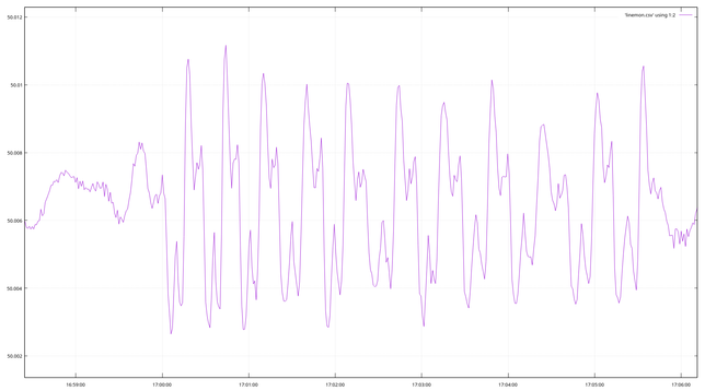
    here's a look at one of the bursts of noise. it looks kinda… regular? not sure what's going on. it also starts at exactly 5pm. coincidence?!

    Periodic oscillation with an amplitude of around 0.08Hz and a period of around 25 seconds
    💬 7🔄 0⭐ 2
  • 💬 1🔄 0⭐ 0
  • Nov 11, 2026, 11:54 AM

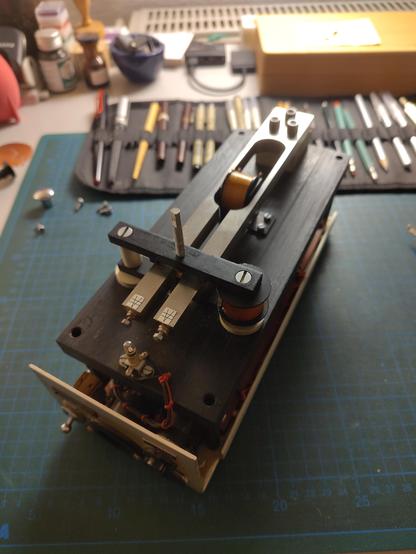
    @f4grx I know, right? It's even better with the cover off!

    The same device as in the original post, but with the cover removed showing the very large tuning fork inside and the thick slab of metal it's mounted on. There are various coils mounted around the tuning fork to measure it's motion and keep it going,
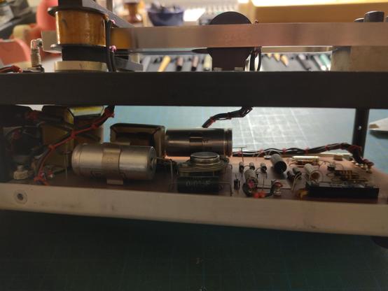
    A view under the thick metal slab holding the tuning fork, revealing the circuit board underneath. It's all very old looking through hole components.
    💬 1🔄 1⭐ 4
  • 💬 1🔄 0⭐ 1
  • 💬 1🔄 0⭐ 1
  • 💬 0🔄 0⭐ 0
  • 💬 1🔄 0⭐ 1
  • 💬 1🔄 0⭐ 0
  • 💬 0🔄 0⭐ 0
  • 💬 1🔄 0⭐ 1
  • Nov 11, 2026, 6:50 PM

    @penguin42 no chiming bells around I think…

    time reference is just the sample clock in my audio interface

    💬 2🔄 0⭐ 2
  • Nov 11, 2026, 6:56 PM

    @slyka @penguin42 how are you measuring the frequency? Fixed threshold, then look for pairs of crossings in the same direction to get the full cycle?

    💬 1🔄 0⭐ 1
  • Nov 11, 2026, 7:01 PM

    @synx508 @penguin42 the signal is downconverted to 0Hz as a complex signal, then the derivative of the phase is averaged over one second. it's basically an FM demodulator.

    💬 1🔄 0⭐ 3
  • Nov 11, 2026, 7:17 PM

    @slyka @penguin42 Interesting. I'm guessing it's a beat between whatever the frequency is and that 1s window, or something *like* that, so triggered when the frequency hits a certain value and you don't end up measuring the frequency because it wobbles. Could be very wrong though. It looks like "a maths" rather than something that is happening.

    💬 1🔄 0⭐ 1
  • Nov 11, 2026, 7:45 PM

    @synx508 @penguin42 yep, that's possible. everything aside from the averaging is completely continuous though, so I could just replace the averaging step with a 1Hz lowpass filter or something to eliminate that possibility

    💬 1🔄 0⭐ 2
  • Nov 11, 2026, 8:21 PM

    @slyka @penguin42 I ran into something similar when I was making a 19kHz pilot level meter in gnuradio, i'm stuck under a cat at the moment and can't reach the machine that's on but I think I solved it with a low pass filter instead of using averaging.

    💬 1🔄 0⭐ 1
  • Nov 11, 2026, 8:24 PM

    @synx508 @penguin42 yeah, the problem is that the frequency response of a non overlapping rectangular window is just… kinda terrible

    💬 0🔄 0⭐ 2
  • Nov 11, 2026, 6:57 PM

    @slyka if it's an audio interface have you thought about putting a different reference clock in on the other channel?

    💬 1🔄 0⭐ 1
  • Nov 11, 2026, 7:04 PM

    @penguin42 I did a measurement of the output frequency of a function generator and got a standard deviation of around 3*10^-6Hz over the course of a few minutes, so I trust the clock in my audio interface. It's a decent studio interface and it should be a pretty good reference clock.

    💬 0🔄 0⭐ 3
  • Nov 11, 2026, 6:31 PM

    @slyka How well is it insulated from noise and vibration?
    Could be some kind of motor or pump on a timer.

    💬 1🔄 0⭐ 1
  • 💬 1🔄 0⭐ 2
  • Nov 11, 2026, 6:52 PM

    @f4grx @marshray yeah, it's very likely that there is some external influence. the tuning fork itself is mounted on a very thick slab of metal and the thing is on rubber feet, but I wouldn't be surprised if it picked up, like… the spin cycle of my neighbors washing machine or something

    💬 3🔄 0⭐ 4
  • 💬 0🔄 0⭐ 1
  • Nov 11, 2026, 7:03 PM

    @slyka @f4grx I suspect that if you looked at the wave itself you would see a spike or distortion that slowly crawled across the cycle over a period of 30s.
    E.g. interference at either 49.97 or 50.04 Hz.

    💬 1🔄 0⭐ 1
  • 💬 2🔄 0⭐ 1
  • Nov 11, 2026, 7:08 PM

    @marshray @slyka the frequency evolution shows in fact a frequency modulation with a chaotic rythm. We could be observing something that is typical of tuning fork oscillators. Maybe torsion or asymmetry of the branches or a beat from the excitation circuit itself. Idk.

    💬 0🔄 0⭐ 1
  • Nov 11, 2026, 7:09 PM

    @f4grx @marshray well, it's probably not what you expect…

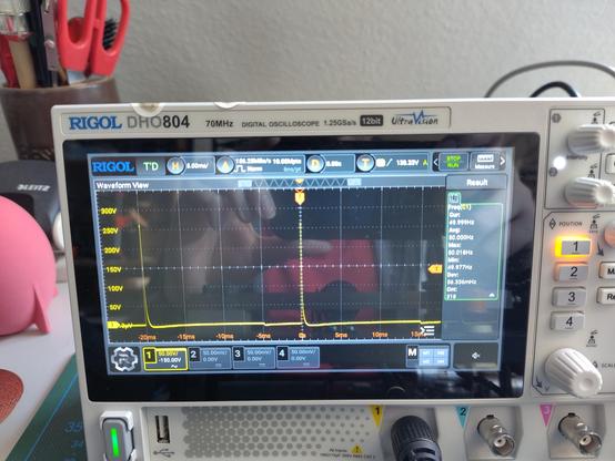
    (I was running it at a lower supply voltage here, at full supply voltage the output peaks at around 350V)

    For the measurement I just divided that down, plugged it into my mixer through some capacitive coupling and turned down the highs and mids and boosted the bass on the EQ. I used a metrology grade EQ, of course.

    Image attached toot
    💬 1🔄 0⭐ 3
  • 💬 1🔄 0⭐ 1
  • Nov 11, 2026, 7:43 PM

    @marshray @f4grx as far as I know this thing was used to fire a strobe on some kind of engine tachometer adjustment machine or something? I don't quite remember. there isn't a lot of information on this thing

    💬 1🔄 0⭐ 3
  • Nov 11, 2026, 7:54 PM

    @slyka @f4grx Oh yes I recall seeing the photos of this device.
    Another possibility is a bad filter capacitor or solder joint intermittently allowing mains hum onto the DC power rails.

    💬 0🔄 0⭐ 0
  • 💬 1🔄 0⭐ 2
  • Nov 12, 2026, 10:56 AM

    @1000millimeter @f4grx @marshray using 60 year old electrolytic capacitors. it looked clean when I checked the the thing out, but since it's all class A amplifiers inside this thing the PSRR is basically 0

    💬 0🔄 0⭐ 3
  • Nov 11, 2026, 6:39 PM

    @slyka This kind of waveform is typical of a chaotic behaviour, can be caused by non linearities, for example from overdrive and departure from linear harmonic approximations. Not all oscillators are well behaved.

    Edit: I did not notice it was frequency variations. Then it is even stranger.

    💬 0🔄 0⭐ 0
  • Nov 11, 2026, 8:20 PM

    @slyka That looks as if something in there would be oscillating mechanically in there.
    I have experimented with the mains frequency and it helps to view the data with Audacity. It allows you to do a spectrogram which might be more revealing.

    💬 1🔄 0⭐ 1
  • Nov 11, 2026, 8:26 PM

    @casandro yeah, I might add something to automatically save chunks of incoming data to disk if it strays too far outside the standard deviation. might be interesting for glitches in the mains frequency too

    💬 1🔄 0⭐ 1
  • Nov 11, 2026, 8:28 PM

    @slyka Well on the mains frequency I've experimented a bit, and there's some stuff that's easy to see.

    For example you can easily see the 15 minute oscillations because of the electricity market. However one can also see much faster oscillations in the order of 1Hz probably caused by oscillations in the European power grid. After all thanks to all those rotating masses, the "speed of light" in the grid is very low, so you get a high group delay. I can get you preliminary data.

    💬 0🔄 0⭐ 1
  • Nov 11, 2026, 8:30 PM

    @slyka wondering if what's happening here is grid load/supply switching and a brief instability as supply comes online. Specifically that possibly the grid coupling goes like this:

    1. Your source starts and slowly wanders down to some lock against the grid
    2. The grid frequency shifts "abruptly" in the sense of a grid, causing a low ampliude beat frequency
    3. It wanders a bit before acquiring a phase lock again (in the mechanical way).

    This is sort of bullshit based on conjecture though and I'm not even sure all parts of that theory align?

    Experiment:
    Use another channel on the input to track grid frequency so that you can capture both with the exact same time reference and you can measure the two together.

    (You can also try correlating against public grid frequency data but as this can theoretically dox someone I would be careful about posting too much detail)

    💬 1🔄 0⭐ 2
  • Nov 12, 2026, 10:59 AM

    @Lunaphied yeah, might give that a try along with all the other stuff suggested in the thread. I don't think it's locking to the grid since the grid is way more chaotic and all over the place, but maybe there is some beat frequency stuff happening if the two frequencies get close?

    💬 0🔄 0⭐ 0
  • Nov 11, 2026, 9:55 PM

    @slyka I wonder if you are seeing zellweger / ripple control signalling coming through. Not sure how your device works or if you have the in your area

    💬 1🔄 0⭐ 1
  • Nov 12, 2026, 11:04 AM

    @xssfox hmm, good question. might have to do a recording of both the oscillator and the mains and see if there is a correlation between these oscillations and *something* happening on the mains.
    The oscillator just runs off of an unregulated 15V supply, so it's not impossible for stuff from the mains to have an effect, especially cause they're so close in frequency

    💬 0🔄 0⭐ 2
  • 💬 1🔄 0⭐ 1
  • Nov 11, 2026, 7:45 PM

    @ferrix my neighbors knock on my door and ask if everything is alright

    💬 0🔄 0⭐ 3
  • 💬 1🔄 0⭐ 1
  • Nov 11, 2026, 6:56 PM

    @f4grx most of those decimals are a lie, but I'm just doing direct frequency measurement by turning the signal into an IQ signal, differentiating the phase and averaging that over one second. when hooking my function generator to my sound card I get a standard deviation of around 3*10^-6Hz over the span of 5 minutes or so.

    💬 0🔄 0⭐ 2
  • 💬 1🔄 0⭐ 1
  • Nov 11, 2026, 2:14 PM

    @penguin42 yes, they really knew how to polish a knob back then!

    💬 0🔄 0⭐ 1