Login
You're viewing the defcon.social public feed.
  • Apr 14, 2026, 4:17 PM

    @llorenzin and I were in Asheville over the weekend and were on campus at AB Tech for an event on Saturday when we saw a sign for the Asheville Radio Museum.

    Following the signs through the building and up to the 3rd floor, we found a lovely museum with working tube radios including the centerpiece Zenith Stratosphere (of which there are only ~40 left in existence). They have a Bluetooth to AM transmitter setup in the museum room so they can play music the radios will pick up, and it sounded amazing!

    They also have a lot of ham (and other) radio gear and a full ham radio station setup in the corner that operates as W4AFM.

    Wonderful little museum, and both the docents we talked to were great! It was fairly random that we were there, the museum was open, and we had the time to stop in. I highly recommend going to the Asheville Radio Museum if you're in town.

    #HamRadio #AmateurRadio #Museum

    Beautiful restored Zenith Stratosphere console radio (of which there are only ~40 left in existence). There is a white ceramic cat sitting upright in the cutout in front of the speakers.
    Left side of the museum with racks of radio and computer equipment.
    Right side of the museum with racks of radio equipment, mostly older table top and floor model receivers, some with vacuum tubes prominently displayed. There are also a few people in the picture.
    Shelves of older equipment from the beginning of the radio era. Across the top shelves are gramophone horns.
    💬 5🔄 23⭐ 11

Replies

  • 💬 0🔄 0⭐ 0
  • Apr 14, 2026, 5:51 PM

    @mbroome @llorenzin In 1985-1986, I actually used a transmitter with a solid state exciter board and a tube driver and final amp for FM pirate radio broadcasting.

    Why? Because the 6146B VHF capable power tube was still available common and cheap at hamfests and two were in the house from a partially disassembed ham trasmitter my father had built a half-century earlier. I didn't have a source for decent VHF power transistors until late 2006.

    💬 1🔄 0⭐ 0
  • Apr 15, 2026, 3:29 AM

    @mbroome @llorenzin That transmitter was built inside the case of an old first generation Compaq portable computer. I had no idea that would later become collectable!

    The former CRT compartment became the power amp compartment, the driver and solid state board on the right. The hard part was this: due to the anodizing, it was a real bear to seal up that case against RF leaks. I had to take an old TV, attach a length of twin-lead to the antenna terminals, and with the transmitter running on dummy load and the TV tuned to Channel 7 probe around the transmitter to find every harmonic leak!

    In the end, all of the vented parts of the case had to be lined with aluminum window screen, and every edge of that screen had to be glued after application to keep loose wires from escaping and creating shorts.

    You do NOT want your pirate radio setup to be the reason someone cannot watch football...

    💬 1🔄 0⭐ 0
  • Apr 19, 2026, 2:37 AM

    @LukefromDC @mbroome wow. That sounds insanely complicated and *really* nifty. I admire your dedication!!
    We have a friend in the UK who was involved in offshore pirate radio in the 1970s, and it sounds like that was an amazing scene... So much creative engineering, it reminds me of your project!

    💬 1🔄 0⭐ 0
  • Apr 19, 2026, 4:21 AM

    @llorenzin @mbroome
    Some of us autistic folks are good at tech stuff including deep-dive R&D and experimentation.

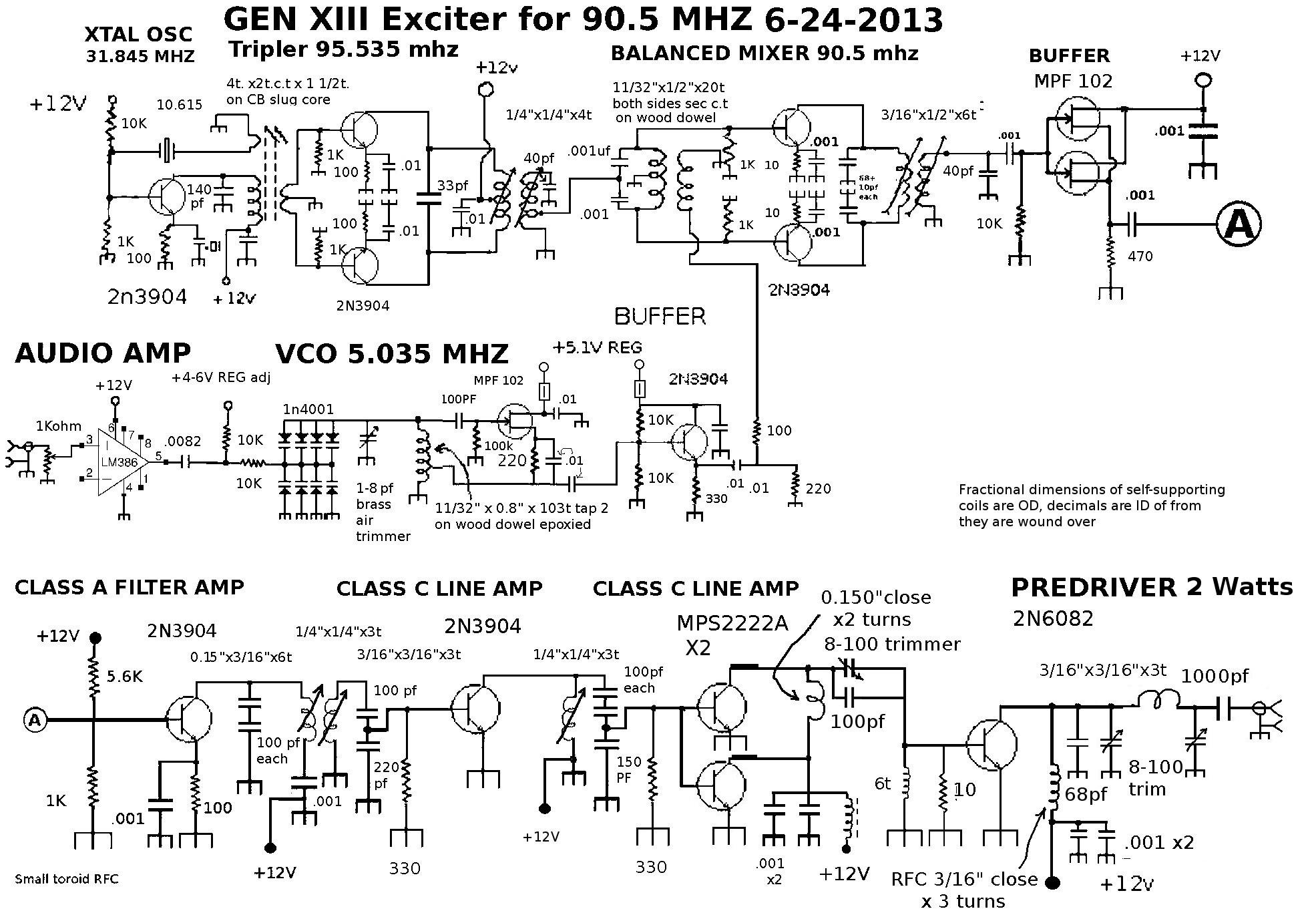
    Construction of all my transmitters was based on and updated from 1960's amateur(ham) radio practice. To get the frequency stability needed in the FM broacsst band I basically reversed the layout of superheterodyne receivera with VFO (variable oacillator) tuning. The low oscillator in the range around 7 MHZ depending on final frequency was modulated wirh opposing ordinary diodes acting as a varacter. The high oscillator was a 3x ovwrtone crystal oscillator at 27 or 32 mhz depending on available crystals.

    The high oscillator went to a tripler and the low oscillator to a buffer stage to isolate it from the mixer. Outputs of these went to the mixer, taking sum or difference depending on crystal to give at first 87.9 and later 88.1 MHZ.

    A critically tuned mixer output and similar highly selective amplifier stages picked out the desired frequency and blocked the other mixer products. This in fact wad the hardest part of the design, as a bad choice of crystal and final output could put undesired mixer products too close to the intended frequency to filter out.

    The common diode ring doubly balanced mixer design did not give a clean enough output. What worked was a singally balanced active mixer wirh a pair of transistors. Low oscillator in push-pull, high oscillator in parallel so the push-pull output tuned circuit would not pass much of it.

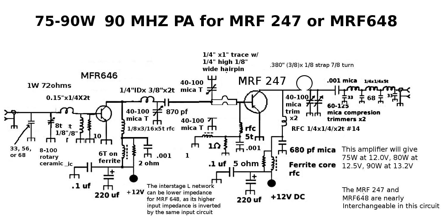
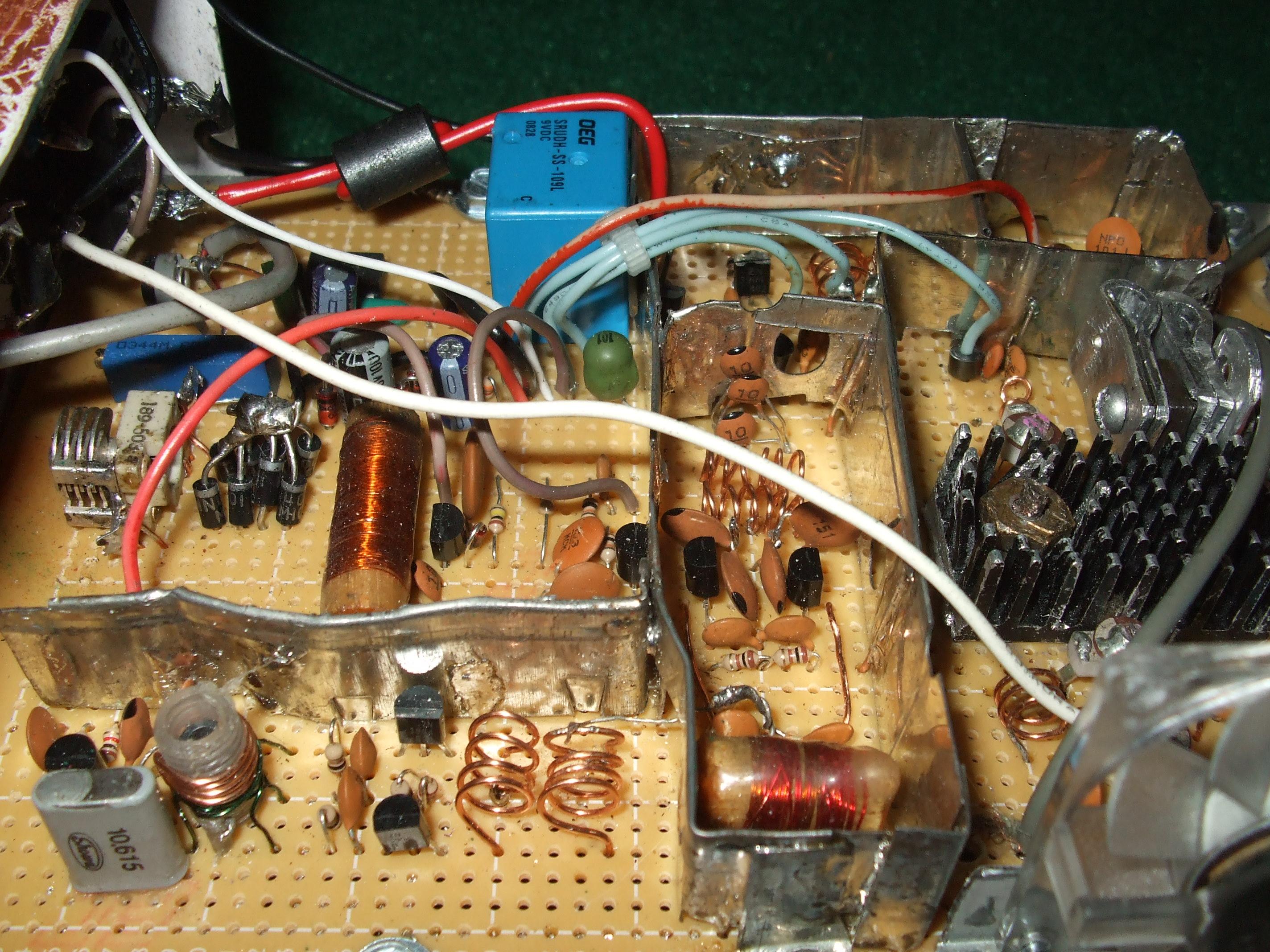
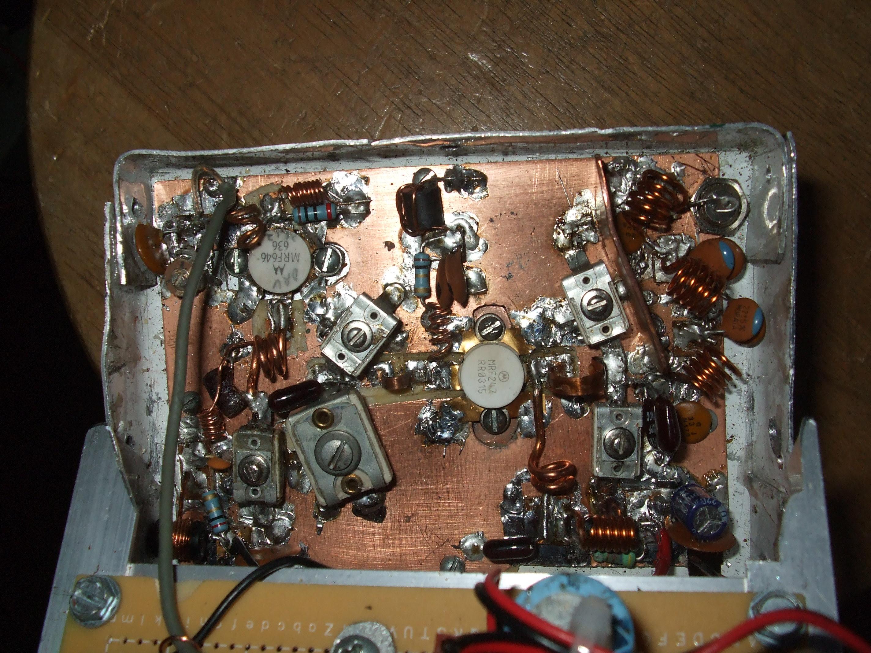
    Finally came that tube driver and dual 6146B push-pull power amp in tje 1995-1996 "Generation 10" design, and in later portable rigs big VHF bipolar power transistors. The tube setup at first made a very inefficient 40-50 watts wirh 440V from a guitar amp transformer (bottoming voltage too high), then with a bit over 500V and some tank circuit work ultimately made about 100W.

    The portable setups were used from the woods on battery power, wirh a 2 half waves in phase antenna pulled 80 feet up a tree wirh a halyard sent up via slingshot.This was after l ran out of fixed base locations.

    All broadcasts were under the callsign "WSQT" or "the squat" on literally squatted Rf spectrum.

    💬 2🔄 0⭐ 0
  • 💬 2🔄 0⭐ 0
  • Apr 21, 2026, 2:40 AM

    @LukefromDC @llorenzin A lot of that sounds like the theory I learned recently to pass the amateur radio General exam. I've done a fair amount of digital circuits in my computer career, but I haven't gotten my hands dirty (yet) with analog heterodyning or amplifying. I agree that it sounds fascinating!

    💬 1🔄 0⭐ 0
  • Apr 21, 2026, 6:24 AM

    @mbroome @llorenzin Analog electronics is a whole different beast than digital.

    Even huge corporations have to experiment to get a new device or circuit to work right from what I've heard.

    My father was a ham in the 1950's-1970's. A whole different era than now, though tube hobbyists keep that flame (or in this case glow) alive to this day.

    The most complex possible project in those days was probably a scratch built multiband tranceiver with both SSB and (good) CW capability, and a VFO that was actually stable. There were never a lot of those from homebuilders from my understanding due to the complexity of a good receiver.

    For me, building a straight superhet receiver would be a lot like building one of those heterodyne transmitters in reverse. Tunes (aligns) almost exactly the same way except for needing an external signal generator to provide an RF source.

    💬 0🔄 0⭐ 0
  • 💬 0🔄 0⭐ 0
  • 💬 1🔄 0⭐ 0
  • Apr 21, 2026, 6:33 AM

    @llorenzin @mbroome

    This is the MRF 247 power amp used with that transmitter. This basic design replaced the tube setup when lighter weight and battery operation (26 pound pack weight) was needed for portable work from the woods.

    This amp gave 75-80W on a freshly charged sealed lead acid battery and could do 100+ if fed from a 13.8V supply (only available in testing).

    Electronic schematic for VHF (FM Broadcast band) power amp
    💬 1🔄 0⭐ 0
  • Apr 21, 2026, 6:36 AM

    @llorenzin @mbroome Inside view of the last WSQT transmitter.

    The high (Xtal) oscillator is bottom left, the low/modulated oscillator at center left. The long compartment in the center is the mixer, and the heatshink on the right is for the 1W predriver stage. Driver and PA or on the other board on the heatsink to the right in this view.

    Internal view of FM broadcast band pirate transmitter
    💬 1🔄 0⭐ 0
  • Apr 21, 2026, 6:40 AM

    @llorenzin @mbroome

    This is the power amp board. The MRF 247 and MRF 648 although two completely different transisters could both be used in this setup, with different tuning of the variable caps and some changes to the inductors. The 247 was tougher and made a little more power, but since it was being run at half its design frequency the internal matching network made it very hard to drive. The MRF 248 is a UHF design to that matching network instead of turning into a mismatch that has to be tuned out has far less effect.

    75W+ power amp for FB broadcast pirate radio transmitter
    💬 1🔄 0⭐ 0
  • 💬 0🔄 0⭐ 0
  • 💬 1🔄 0⭐ 0
  • 💬 0🔄 0⭐ 0
  • 💬 0🔄 0⭐ 0
  • 💬 0🔄 0⭐ 0