Hello #hamradio #electronics folks, maybe you can help me - I have a serious problem in my understanding of RF power transformers.
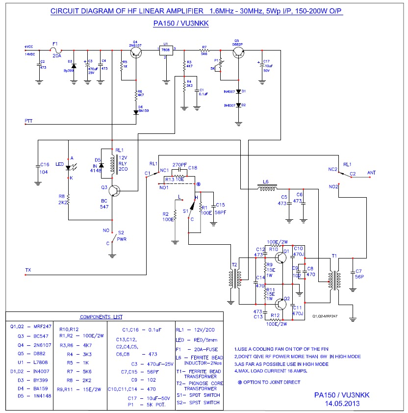
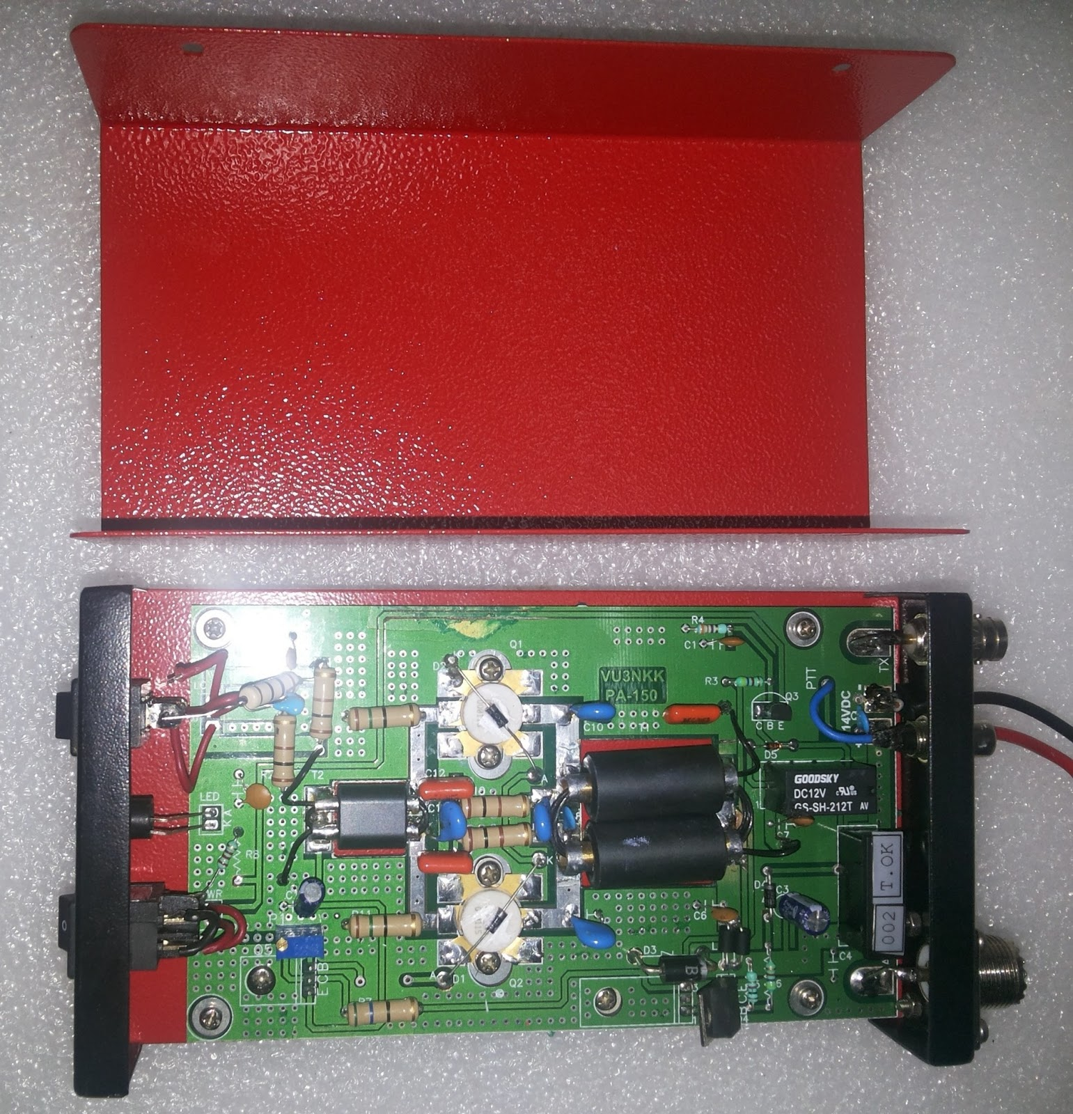
Often you see designs that have two ferrite sleeves, and there is a copper or brass tube on each side forming the primary windings connected to the transistors, along the lines of the attached picture.
Now, in push pull designs I've often seen proposals which use the left brass tube as the primary winding for Transistor 1, and the right brass tube as the primary winding for Transistor 2. The secondary windings go through both holes.
Now, my problem with this construction is the following: if I have one transistor on for each half wave and one transistor off, one of the brass tubes ideally is always an open circuit. This means that the secondary windings going through that side basically form a high impedance ferrite choke with no induction from a primary. The result being that the output impedance is gigantic and no powerful current can form.
So in my mind, this design does not work, or if it does, only by coincidence when mosfet drain output impedances are low even in the off state because of output capacitance.
What am I missing?