Aedan Cullenaedancullen@treehouse.systems
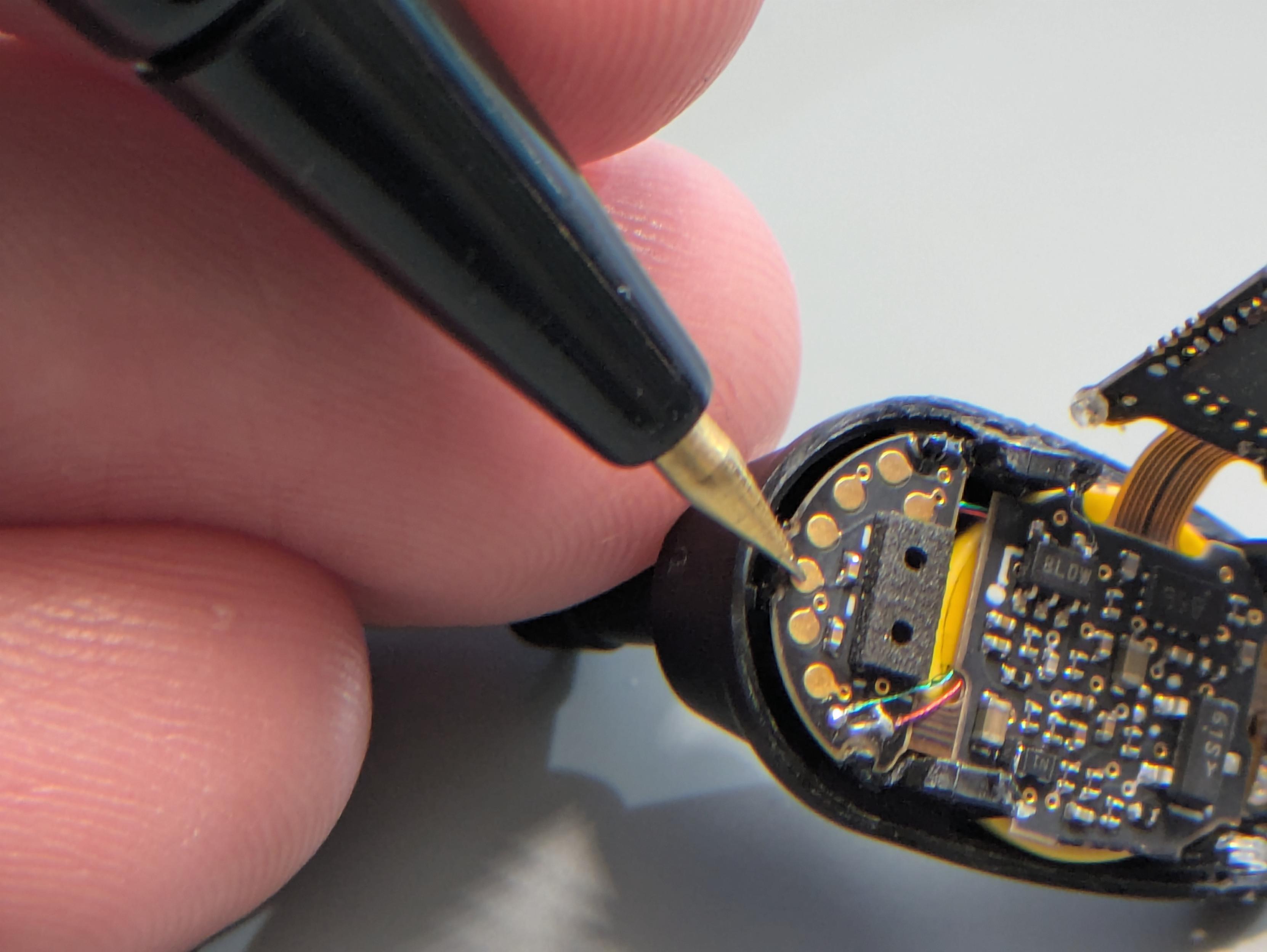
Mar 14, 2026, 5:47 AMThe third test pad from the left is ground, and I found an always-on ~3.55V (iirc) on this via... except not always: the problem seems to be an intermittent battery connection.
6/

The third test pad from the left is ground, and I found an always-on ~3.55V (iirc) on this via... except not always: the problem seems to be an intermittent battery connection.
6/
The battery terminals are soldered to a flex section that descends from the center rigid section. They've put this row of three vias (on the right side of the photo, center one filled with solder) to try to accommodate wherever the battery's positive tab is.
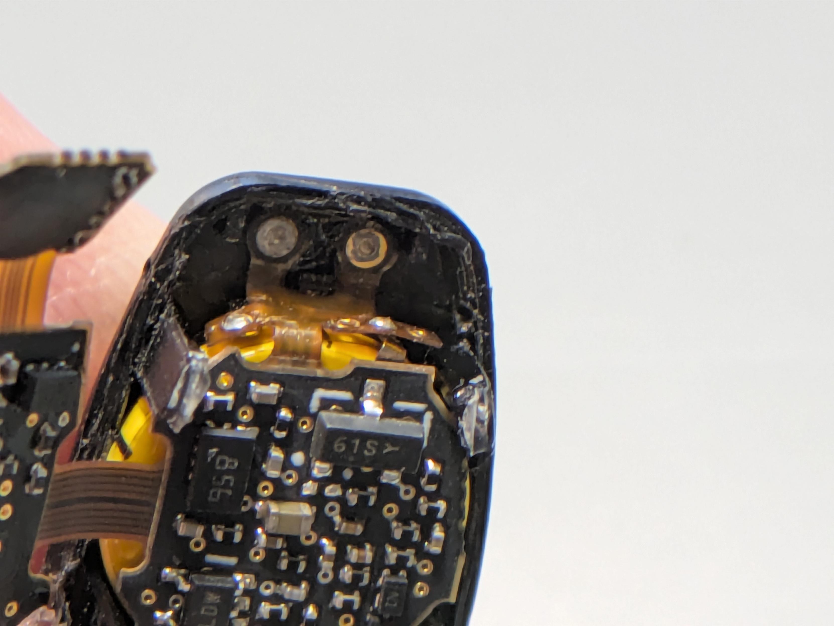
Fortunately, the problem was simply that this solder connection broke!
You can also see the two pass-through charging studs where the case's pogo pins make contact on the outside of the enclosure. (They're not directly across the battery; the charging supply has its own trace on the flex.)
7/
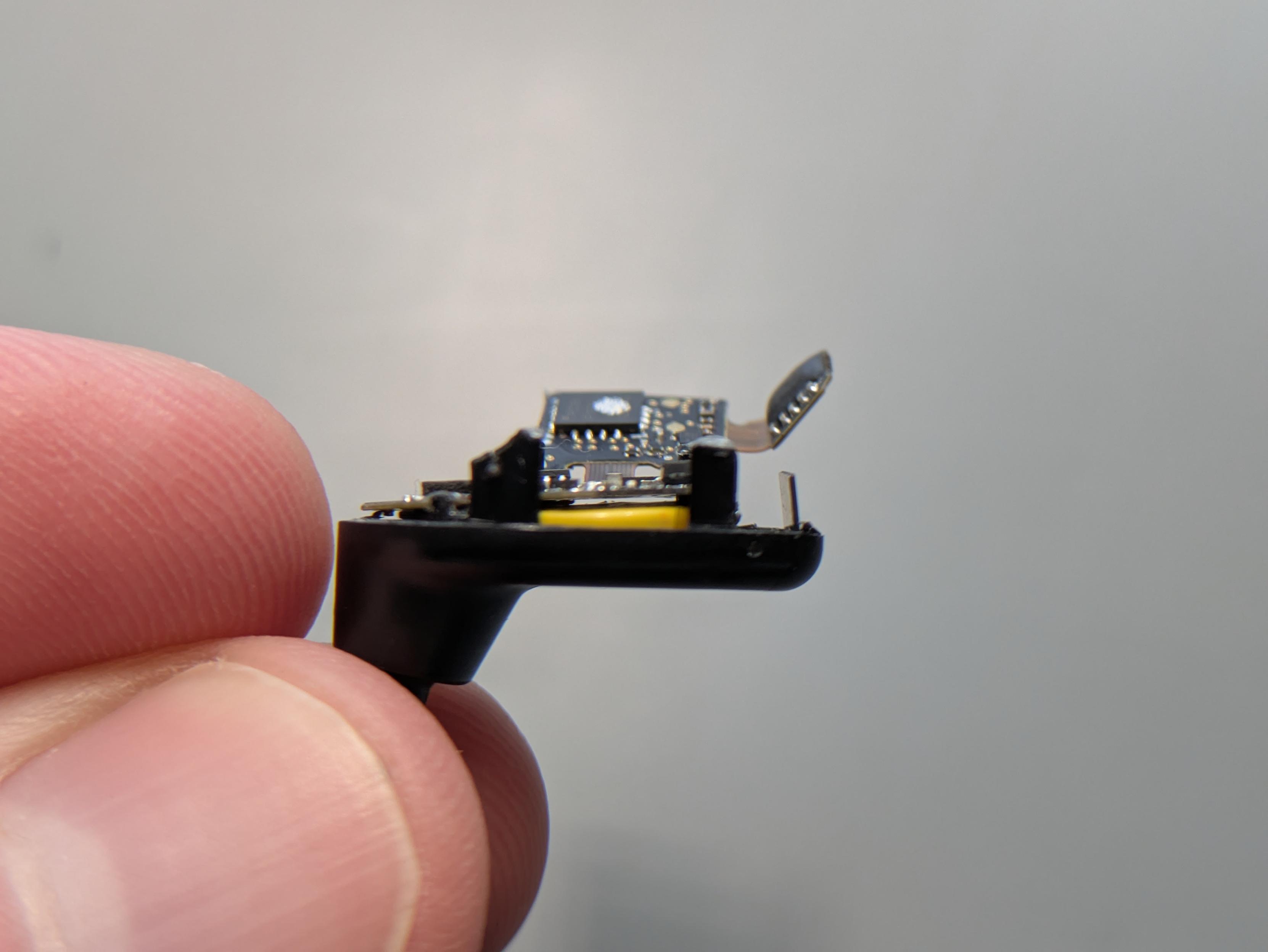
I'm pretty sure this failed because the center board section closest to the battery is not attached solidly to anything; it's entirely supported by flex. It floats freely between the plastic posts that the upper stacked section is glued atop. (See the gap between it and the battery.)
When dropped, it probably oscillates up and down and stresses the soldered battery-tab connections. (Especially if they're cold joints :)
8/
After fixing that solder joint and reassembling everything with a little glue, it's good to go.
9/